
mill control circuit diagram manufacturer Grasping strong production capability, advanced research strength and excellent service, Shanghai mill control circuit diagram supplier create the value and bring values to all of customers.
 WhatsApp)
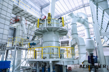
Wiring diagrams. Wiring diagrams show the connections to the controller. Wiring diagrams, sometimes called "main" or "construction" diagrams, show the actual connection points for the wires to the components and terminals of the controller. Basic wiring for motor control – Technical data
DC Mill Type Relays are constructed for steel panel mounting with front connections. Each unit circuit blocks is two pole double break design with captive mounting screws and are interchangeable between relays. DC overload relays are designed for use on dc power circuits to monitor dc motor loading.
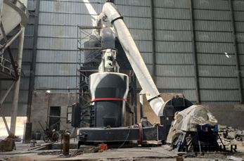
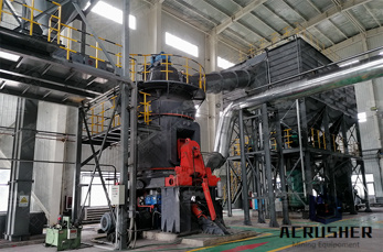
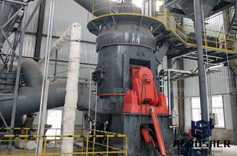
MILL FEED CONTROL. Smooth operation of a milling circuit is difficult to achieve due to: • The varying nature of the feed material (size, ore hardness, etc.). • The unfavorable dynamics between feeders and the weightometer. These dynamics degrade the performance of PID controllers, making feed optimisation more challenging.
Improper wiring can Kill, Injure, Start Fires, Burn Out Motors or any/all of the above. 3ph Starter/3ph Motor¶ Line Voltage Control three phase (3ph) motor starter controlling a three phase motor (rev 08 Aug 2006) The above wiring diagram assumes your magnetic starter has a 240V coil.
wiring diagram calls for something different. It is your job to improvise a solution! file 00836 Question 4 Interpret this AC motor control circuit diagram, explaining the meaning of each symbol: L1 L2 Run M1 To 3phase motor power source M1 Also, explain the operation of this motor control circuit. What happens when someone actuates the ...
When including a PLC in the ladder diagram still remains. But, it does tend to become more complex. Figure 5 below shows a schematic diagram for a PLC based motor control system, similar to the previous motor control example. This figure shows the Estop wired to cutoff power to all of the devices in the circuit, including the PLC. All critical ...
Wiring Diagram Book A1 15 B1 B2 16 18 B3 A2 B1 B3 15 Supply voltage 16 18 L M H 2 Levels B2 L1 F U 1 460 V F U 2 ... NEMA and IEC Markings and Schematic Diagrams.....4 Control and Power Connection Table 4 ... Examples of Control Circuits.....6 2Wire Control 6 3Wire Control 69 Shunting Thermal Units During Starting Period 10 Overcurrent ...
This diagnostic trouble code (DTC) is set when the vehicle''s Powertrain Control Module detects a fault with the Malfunction Indicator Lamp (MIL) electrical circuit. The MIL is commonly referred to as the "Check Engine Light" or "Service Engine Soon" light. MIL is the correct term, however.
Three Phase Motor Power Control Diagrams; Modification in the Electrical Interlocking Control Circuit. This is a simple electrical interlocking circuit. Lots of circuits similar to this interlocking circuit are used in industries. The circuit interlocking depends on the nature of .
An electric circuit is a closed loop with a continuous flow of electric current from the power supply to the load. Here are ten simple electric circuits commonly found around the home. Electric circuits like AC lighting circuit, battery charging circuit, energy meter, switch circuit, air conditioning circuit, thermocouple circuit, DC lighting circuit, multimeter circuit, current transformer ...
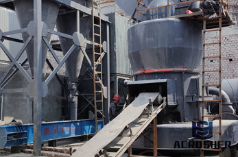
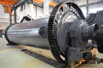
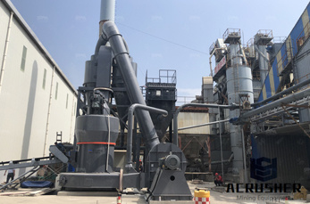
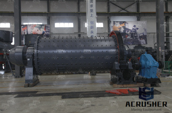
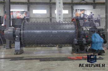
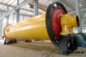
commonly used control strategies are analyzed and discussed. Keywords: Ball mills, grinding circuit, process control. I. Introduction Grinding in ball mills is an important technological process applied to reduce the size of particles which may have different nature and a wide diversity of physical, mechanical and chemical characteristics.
These diagrams are current at the time of publication, check the wiring diagram supplied with the motor. These diagrams apply to INTELLIGENT CONTROL MOTORSthat are fitted to the following products:Pgs OCD/EEC.. Gamma EC D50/51 Diags. IC1, 2 .
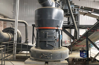
High quality circuit boards can be produced using either process. In the case of PCB milling, the quality of a circuit board is chiefly determined by the system''s true, or weighted, milling accuracy and control as well as the condition (sharpness, temper) of the milling bits and their respective feed/rotational speeds.
A power circuit provides significant electrical capacity to operate something that does a lot of work, for example high power heaters or multihorsepower motors. There is a load or loads that consume X watts of power to perform a function. In the ...
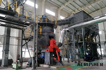
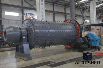
Advanced Controller for Grinding Mills: Results from a Ball Mill Circuit in a Copper Concentrator Anoop Mathur, Sujit Gaikwad, ... Results of using this advanced controller on a ball mill circuit operation in a copper ... BALL MILL CONTROL EXAMPLE Process Description
A circuit diagram (electrical diagram, elementary diagram, electronic schematic) is a graphical representation of an electrical pictorial circuit diagram uses simple images of components, while a schematic diagram shows the components and interconnections of the circuit using standardized symbolic representations. The presentation of the interconnections between circuit .
Wiring diagram for standard MicroMark 7x14 mini lathe. XMT1135 LMS 2040: 2514: Wiring diagram for late model mini mill with red and yellow emergency stop switch. FC350BJ/110V LMS 1211: 3156: Wiring diagram for late model harbor freight mini lathe with illuminated rocker power switch and safety interlock circuit. FC250BJ/110V LMS 3149
Type 6011 DC Mill Type Relays are recommended for use in control circuits for mill duty control systems. Type C304 inverse time and instantaneous DC Magnetic Overload Relays with automatic reset are designed for use in dc motor circuits to monitor dc motor loading.
Easy to Build CNC Mill Stepper Motor and Driver Circuits: This is a follow up to the Easy to Build Desk Top 3 Axis CNC Milling Machine Once you get the machine all put together its time to make it go. So it''s time to drive the motors. And here I''ve put together a circuit that I think is the absolute che...
Are you fed up with ordinary PWM circuits which do not provide perfect DC motor speed control especially at lower speeds? Then check out this outstanding single chip PWM motor speed controller circuit that will give you a complete 360 degrees of continuously varying motor speed control right from zero to maximum. The speed is controlled through an externally applied varying DC voltage source.
Based on your observations of these two diagrams, explain how electromechanical relays are represented differently between ladder and schematic diagrams. Interpret this AC motor control circuit diagram, explaining the meaning of each symbol: Also, explain the operation of this motor control circuit ...
Jul 25, 2012· Hi all, where can I find a wiring diagram for a Bridgeport built by Textron. On the electrical panel box attatched to the machine the nameplate says Drawing No. WD153D I am firing up the mill and finding that in high speed the contactor will pop out and stop the motor about 1 minute into running it ...
Aug 14, 2002· Motor and general control electronic circuit diagrams / circuit schematics. Note that all these links are external and we cannot provide support on the circuits or offer any guarantees to their accuracy. Some circuits would be illegal to operate in most countries and others are dangerous to construct and should not be attempted by the ...
Dec 09, 2015· Common voltage values for motor starter coils (in volts AC) are: 24, 120, 208, 240, 277, 480, and 560. A twowire line voltage control circuit is shown in Figure 18–5. ThreeWire Control Circuits. Threewire control circuits are characterized by .
WhatsApp)