
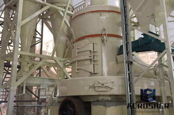
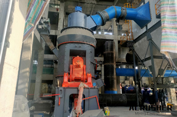
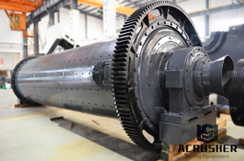
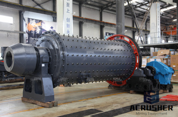
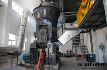
temperature control circuit diagram for ball mill using rtd sensor manufacturer Grasping strong production capability, advanced research strength and excellent service, Shanghai temperature control circuit diagram for ball mill using rtd sensor supplier create the value and bring values to all of customers.
 WhatsApp)
mistors in Single Supply Temperature Sensing Circuits", DS00685. Finally, the signalconditioning path for the RTD system will be covered with application circuits from sensor to microcontroller. FIGURE 1: Unlike thermistors, RTD temperaturesensing elements require current excitation. RTD OVERVIEW The acronym "RTD" is derived from the ...
Omega''s load cells are compact, rugged, and constructed with the highest quality alloy steel. We have an array of different load cells available, including bending beam models, platform load cells for washdown applications, canisters, minibeam load cells, and more.
The idea behind 420 mA current loop operation is that the sensor draws current from its power source in direct proportion to the mechanical property it measures. Take the example of a 100 psi sensor with a current loop output. With 0 psi applied, the sensor draws 4 mA from its power source. With 100 psi applied the sensor draws 20 mA.
The trigger input reacts to a rising edge. A low level at the trigger input forces the output of the timer low. R3 and C3 have therefore been added, to make the control range as large as possible.
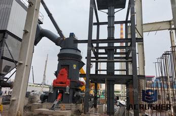
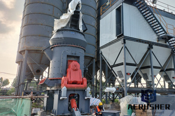
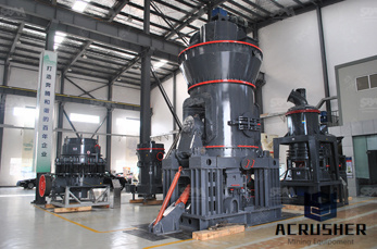
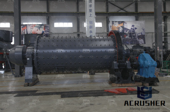
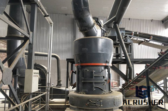
circuit diagram for ball mill using rtd sensor diagram of a ball mill circuit grinding mill equipment. temperature control circuit diagram for ball mill using PRODUCTS Power Engineering temperature control circuit diagram for ball mill using rtd sensor 1 Nov 2001 Marwin Valve has introduced the AM3000 series three piece heavyduty ball valve designed specifically for In ...

Note: In this publication the line diagrams show the control circuits only power circuits are omitted for clarity, since they can be traced readily on the wiring diagrams (heavy lines). A wiring diagram gives the necessary information for actually wiringup a group of control devices or for
concerning the thermistor temperature sensor, refer to Microchip''s AN685, "Thermistors in Single Supply Temperature Sensing Circuits" [ 7]. Finally, the signalconditioning path for the RTD system will be covered with application circuits from sensor to microcontroller. FIGURE 1: RTD Temperaturesensing Elements Use Current Excitation ...
This basic light sensor circuit is of a relay output light activated switch. A potential divider circuit is formed between the photoresistor, LDR and the resistor no light is present ie in darkness, the resistance of the LDR is very high in the Megaohms (MΩ) range so zero base bias is applied to the transistor TR1 and the relay is deenergised or "OFF".
LM35 Temperature Sensor Circuit Diagram. Malik. ... German Maker Norbert Heinz shows how to create a homemade CNC mill using inexpensive chipboard and repurposed computer CD drives. ... Electronic Schematics Control System Electronics Projects. Almost a years ago, I post the first version of a simple temperature control system ultilizing only a ...
RTD Sensors. Solid State Sensors. Thermistors. Thermocouple Probes. Surface Sensors ... Temperature measurement generally meets the "simple apparatus" rule although temperature transmitters may be needed to send thermocouple signals over longer distances. ... A system designed to be intrinsically safe requires full documentation of all the ...
RTD sensors are measured with a precision 24bit A/D (analog to digital converter) with builtin programmable gain amplifier. Connections for 2wire RTDs, 3wire RTDs, and 4wire RTDs are shown. Connecting and measuring RTDs with amplifiers and data acquisition systems. Precision RTD .
SparkFun Inventor''s Kit Experiment Guide ... language:cpp /* SparkFun Inventor''s Kit Circuit 3BDistance Sensor Control the color of an RGB LED using an ultrasonic distance sensor. This sketch was written by SparkFun Electronics, with lots of help from the Arduino community. ... Circuit 4B: Temperature Sensor.
The LM35 series are precision integratedcircuit temperature devices with an output voltage linearlyproportional to the Centigrade temperature. The LM35 device has an advantage over linear temperature sensors calibrated in Kelvin, as the user is not required to subtract a large constant voltage from the output to obtain convenient Centigrade ...
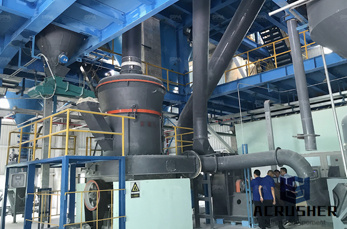
circuit diagram for ball mill using rtd sensor ball mill electrical control circuit diagrams cemtec cement ball mills diagram YouTube 14 Dec 2013 cemtec cement ball mills diagram 2 is a schematic diagram of a ball millcyclone control system Online Service circuit diagram for ball mills and rod mill .
There are four types of temperature sensors that are most commonly used in modernday electronics: thermocouples, RTDs (resistance temperature detectors), thermistors, and semiconductor based integrated circuits (IC). This blog focuses on these four main types of temperature sensors, considerations for each type, advantages, and disadvantages.
These temperature probe assemblies are all constructed using a stainless steel sheath containing either a J or K type thermocouple or a P100 RTD sensor element. The aluminium head contains a programmable 420mA transmitter which, although preprogrammed for the standard ...

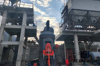
Ballmill instumintion control circuit diagram ball mill and sag circuit mining diagram rod, ball and attrition mills [Chat Online] schematic diagram of comminuting mill rockislandcoza. FIG 7 is a schematic diagram of an electric control circuit for, schematic diagram of hammer mill schematic diagram of hammer mill show the parts of the mill.
A precision interface for a Resistance Temperature Detector (RTD) Walter Bacharowski, Staff Applications Engineer Resistance Temperature Detectors (RTDs) are temperature sensors that make use of the temperature dependence of a metal''s resistance. They are used in a wide variety of temperature measurement and control instrumentation. These circuits
Aug 29, 2019· This change in the temperature of the element being directly proportional to the heat, provides a direct reading of the applied temperature levels. The article explains how rtds work and also how to make a simple high temperature sensor circuit using a homemade RTD device.
Another influence to be aware of is temperature. Both magnets and reed sensors become more magnetic at low temperatures and less magnetic at high temperatures. The amount of change with temperature depends on the type of magnet and reed switch used. There are many types and options of reed sensors that are available.
Apr 12, 2001· There are 2777 circuit schematics available. The Last circuit was added on Sunday, November 5, note some adblockers will suppress the schematics as well as the advertisement so please disable if the schematic list is empty.
b) Stator winding temperature sensor c) Stator air sensor d) Stator vibration sensor ROTOR Revolving fieldcoil Excitation armature Fan (machines: IC 0 A1) Rotating diode bridge a) General points b) Tightening torque for the rotating diode fastening screws c) .
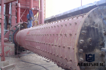
How To Calculate Residence Time In A Ball Mill. TECHNICAL NOTES 8943 Кб. Figure Residencetime distribution function for solids in a continuously operating ball the mill and examining how the specific power input varies with mill size and with design and () To size a ball mill or rod mill that must process W tons/hr it is necessary to calculate...
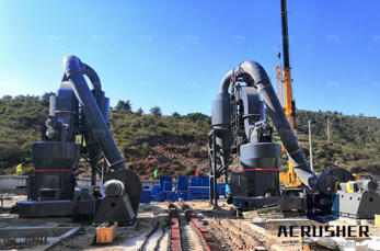
201423Advanced Controller for Grinding Mills: Results from a Ball Mill Circuit in a Copper Concentrator Anoop Mathur, Sujit Gaikwad, MILL CONTROL: BALL MILL CONTROL EXAMPLE Process Description The copper concentrator in Pinto Valley, Arizona processes a 0 4% grade copper ore from a nearby open ... internals and for dedusting If temperature of ...
WhatsApp)